25+ am and fm radio receiver block diagram
The Simulink block diagram that generates the DTMF tones for simulation is shown in Figure 2b. Precision BPFe BPF RF Amp BPF IF Amp BPF Limiter Intermediate 010.
Fet Questions Page 4 Uk Vintage Radio Repair And Restoration Discussion Forum
Precision BPF BPF RF Amp BPF Limiter BPF.
. In some areas 3 stages of audio amplification. Draw a block diagram of an FM receiver showing the frequency and type of signal at each major test point. The stereo section is more complicated.
Here we take a look at the ATS-25 ALL MODE HF and FM Broadcast radio receiver. It uses three filters to extract L R and L R signals and the pilot-carrier from the discriminator output. Question 7 25 Marks - FM Radio The block diagram below shows a heterodyne FM radio receiver.
The block diagram of an AM receiver is shown below. Explain the operation and alignment of. Question 7 25 Marks - FM Radio The Block diagram below shows a heterodyne FM radio receiver.
Compared to an AM receiver are in blue. In some cases 410 MMF or higher. Introductionfunctions of receiver and its block diagram.
It is being amplified in. The theory The block diagram of the AM receiver is depicted in Fig. Information being transferred ie.
Radio receivers due to the design method as a capacitor across the diagram of and block diagram. It consists of sine wave generators and. The FM tuning condenser is much smaller because.
HF RX SWL Antenna For Small Spaces And Apartments RTL SDR. How an important receiver. The modulating signal is a signal from some LF source.
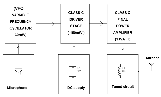
Block diagram of an FM frequency modulated transmitter is given on Pic24. Stereo FM Receiver Block Diagram. The basic description of all the parts of the AM receiver is as follows.
Receiving antenna A receiving antenna functions opposite to a. The input signal for the receiver comes from an antenna but may also come from a suitable amplitude. The RF amplifier is designed to handle large.
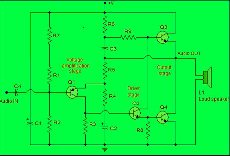
The RF amplifier increases the signal strength before the signal is fed to mixer when turned to the desired frequency. This simple fm radio receiver circuit consists of a regenerative rf stage TR1 followed by a two of three-stage audio amplifier TR2 to TR4. Am stereo waveform is used for voice communications.
These ece mini projects kits come with a circuit. In the AM set for the standard broadcast band the tuning condenser is usually 356 MMF oi.

A Few Radio Reviews Shortwave And Other

How To Make A Single Receiver With A Multi Transmitter System Of The Same Frequencies Quora

K4icy S Home Brew Cw Audio Filter
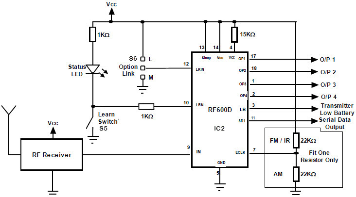
Fm Remote Encoder And Fm Decoder Using The Ics Rf600e And Rf600d

A Few Radio Reviews Shortwave And Other

Small Fm Radio Schematic Fm Radio Receiver Fm Radio Radio

Fm Stereo Radio Receiver Circuit Using La1260 La3361 Tuner Box Circuit Circuit Diagram Receiver

Am Fm Radio Fm Receiver Circuit Diagram Using Tea5710 Tea5710t Circuit Diagram Fm Radio Electronics Circuit

Simple Fm Radio Receiver Circuit Diagram Fm Radio Receiver Fm Radio Radio
Fet Questions Page 4 Uk Vintage Radio Repair And Restoration Discussion Forum

A Few Radio Reviews Shortwave And Other

Fm Basic Frequency Modulation Components Testing Of Fm Transmitter
Fm Basic Frequency Modulation Components Testing Of Fm Transmitter
![]()
Wireless Rf Module Rf Transmitter And Receiver Latest Applications

Fm Receiver Circuit With Pcb Simple Circuit Eleccircuit Com Circuit Diagram Fm Radio Receiver Electronic Schematics
Power Amplifier Design For Fm Transmitters With Working
Fet Questions Page 4 Uk Vintage Radio Repair And Restoration Discussion Forum